- 您现在的位置:买卖IC网 > Sheet目录506 > SCA3000-E05 (Murata Electronics Oy)ACCELEROMETER 3-AXIS +/-18G SPI
SCA3000-E05
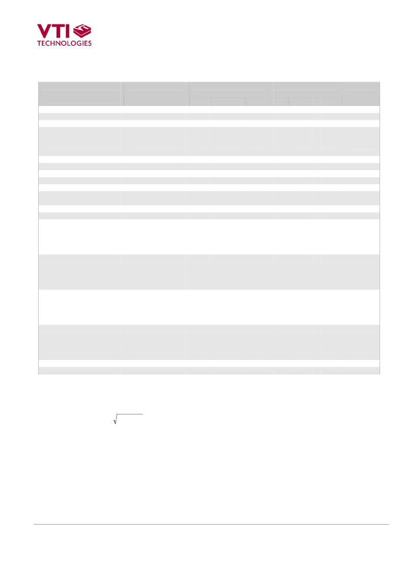
Performance Characteristics 1)
Parameter
Condition
Typical supply range
2.35 – 2.7 V
Min Typ 2)
Max
Extended supply
range 2.7 – 3.6 V
Min Typ 2) Max
Units
Analog and digital Vdd
2.35
2.5
2.7
-
3.3
-
V
Bandwidth **
Digital I/O Vdd
Operating temperature **
Current consumption *
Acceleration range * 4)
Offset calibration error *
Offset temperature error ** 5)
Sensitivity * 6)
Sensitivity calibration error *
Sensitivity temperature error
** 7)
Non-Linearity ** 8)
Cross-Axis sensitivity ** 9)
10)
Vdd ≥ Digital I/O Vdd
Reset 3)
Active
Motion Detection
mode
Nominal
Z-axis +1g position
-40 ... +85 °C
-40 ... +85 °C
Measurement mode
Narrow band
1.7
-40
-
-
-
-18
-300
-30
-
-11
-0.05
-3
-
45
7
1.8 / 2.5
-
<7
120
120
-
-
±5.0
160
-
±0.015
±1
±4
60
9
2.7
85
12
145
145
18
300
+30
-
+11
0.05
3
-
75
11
-
-40
-
-
-
-
-
-
-
-
-
-
-
-
-
3.3
-
<9
150
150
± 18
± 500
±5.0
160
±2
±0.015
±1
±4
60
9
-
85
-
-
-
-
-
-
-
-
-
-
-
-
-
V
°C
μ A
μ A
μ A
g
mg
mg/°C
Count/g
%
%/°C
% FS
%
Hz
Hz
measurement mode
Wide band
50
75
100
-
70
-
Hz
Noise ** 11)
measurement mode
Measurement mode
Narrow band
-
-
50
22
100
44
-
-
50
22
-
-
mg RMS
mg RMS
measurement mode
Wide band
-
65
130
-
65
-
mg RMS
measurement mode
Output data rate **
Measurement mode
Narrow band
160
40
200
50
240
60
-
-
200
45
-
-
Hz
Hz
measurement mode
Wide band
320
400
480
-
400
-
Hz
Turn on time ** 12)
measurement mode
Measurement mode
Narrow band
-
-
30
200
60
400
-
-
30
200
-
-
ms
ms
measurement mode
Wide band
-
20
40
-
20
-
ms
measurement mode
Output load **
SPI clock rate **
-
-
-
-
35
325
-
-
-
-
35
325
pF
kHz
x 2 + y + z 2 ≤ 18 g . The measuring range is tested on sensing element level. FS = 18g.
*
**
1)
2)
3)
4)
5)
6)
7)
8)
9)
10)
100% tested in production
Qualified during product validation
The product is factory calibrated at 2.5 V in room temperature.
Typical values are not guaranteed.
Includes the current through the internal 400 k ? pull-up resistor connected to digital I/O Vdd.
Range defined as 2
Offset temperature error = {Count(0g)-Offset} / Sensitivity [ g ]. Sensitivity = Calibrated sensitivity.
Offset= Calibrated offset.
Sensitivity = {Count(+1g) - Count(-1g)}/2 [Count/g].
Sensitivity temperature error = {[Count(+1g)-Count(-1g)]/2 - Sensitivity} / Sensitivity x 100% [%].
Sensitivity = Calibrated sensitivity.
From straight line through sensitivity calibration (+1g, -1g) points.
The cross-axis sensitivity determines how much acceleration, perpendicular to the measuring axis, couples to
the output. The total cross-axis sensitivity is the geometric sum of the sensitivities of the two axes which are
perpendicular to the measuring axis. The angular alignment error between X, Y and Z axis is included into the
cross axis sensitivity.
Frequency responses according to Figure 3 , Figure 4 and Figure 5 .
VTI Technologies Oy
2/4
www.vti.fi
Doc. Nr. 8269100B.0
Rev.B.0
发布紧急采购,3分钟左右您将得到回复。
相关PDF资料
SCA610-CAHH1G
ACCELEROMETER SNGL 0.5G DIL8 SMD
SCH1331-TL-H
MOSFET P-CH 12V 3A SCH6
SCH1332-TL-H
MOSFET P-CH 20V 2.5A SCH6
SCH1333-TL-H
MOSFET P-CH 20V 2A SCH6
SCH1343-TL-H
MOSFET P-CH 20V 3.5A SCH6
SCH1433-TL-H
MOSFET N-CH 20V 3.5A SCH6
SCH1439-TL-H
MOSFET N-CH 30V 3.5A SCH6
SD101201
SENSOR GEARTOOTH SPEED PLASTIC
相关代理商/技术参数
SCA3000-E05 PWB
功能描述:BOARD PWB W/SCA3000-E05 RoHS:是 类别:编程器,开发系统 >> 评估板 - 传感器 系列:180 产品培训模块:Lead (SnPb) Finish for COTS
Obsolescence Mitigation Program 标准包装:1 系列:-
SCA3060
制造商:MURATA 制造商全称:Murata Manufacturing Co., Ltd. 功能描述:Digital Low Cost Low Power Automotive Qualified 3-axis Accelerometer
SCA3060-D01
功能描述:ACCELEROMETER 3-AXIS +/-2G SPI RoHS:是 类别:传感器,转换器 >> 加速计 系列:- 标准包装:1 系列:SCA1000 轴:X,Y 加速范围:±1.7g 灵敏度:1.2V/g 电源电压:4.75 V ~ 5.25 V 输出类型:数字 带宽:50±30Hz 接口:SPI 安装类型:表面贴装 封装/外壳:12-SMD 供应商设备封装:12-SMD 其它名称:551-1007-1
SCA3060-D01 DEMO
功能描述:加速传感器开发工具 SCA3060-D01 Demo Board RoHS:否 制造商:Murata 工具用于评估:SCA3100-D04 加速:2 g 传感轴:Triple Axis 接口类型:SPI 工作电压:3.3 V
SCA3060-D01 PWB
功能描述:加速传感器开发工具 SCA3060-D01 Daughter PCB RoHS:否 制造商:Murata 工具用于评估:SCA3100-D04 加速:2 g 传感轴:Triple Axis 接口类型:SPI 工作电压:3.3 V
SCA3060-D01-004
制造商:Murata Manufacturing Co Ltd 功能描述:
SCA3060-D01-1
功能描述:加速计 - 板上安装 Lo Pwr 3-Axis Accel Auto Qualified
RoHS:否 制造商:Murata 传感轴:Double 加速:12 g 灵敏度: 封装 / 箱体: 输出类型:Analog 数字输出 - 位数:11 bit 电源电压-最大:5.25 V 电源电压-最小:4.75 V 电源电流:4 mA 最大工作温度:+ 125 C 最小工作温度:- 40 C
SCA3060-D01-10
功能描述:加速计 - 板上安装 Lo Pwr 3-Axis Accel Auto Qualified RoHS:否 制造商:Murata 传感轴:Double 加速:12 g 灵敏度: 封装 / 箱体: 输出类型:Analog 数字输出 - 位数:11 bit 电源电压-最大:5.25 V 电源电压-最小:4.75 V 电源电流:4 mA 最大工作温度:+ 125 C 最小工作温度:- 40 C
